Overview
In this lesson, we will learn how to control an LED bar graph by programming the Arduino.
Components
- 1 * Arduino UNO
- 1 * USB Cable
- 1 * 10kΩ Potentiometer
- 10 * 220Ω Resistor
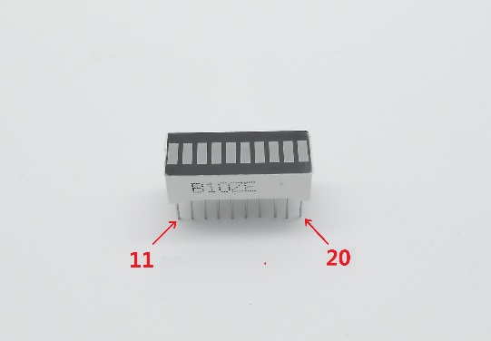
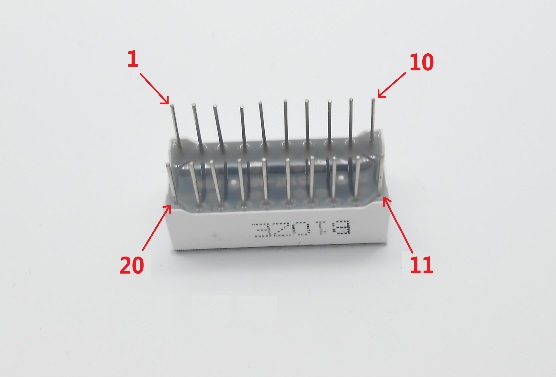
- 1 * LED Bar Graph
- 1 * Breadboard
- Several jumper wires
Principle
The bar graph - a series of LEDs in a line, as you can see on an audio display, is a common hardware display for analog sensors. It's made up of a series of LEDs in a row, an analog input like a potentiometer, and a little code in between. You can buy multi-LED bar graph displays fairly cheaply. This tutorial demonstrates how to control a series of LEDs in a row, but can be applied to any series of digital outputs.
This tutorial borrows from the For Loop and Arrays tutorial as well as the Analog Input tutorial.
The sketch works like this: first read the input. Map the input to the output range which is 0-10 in this case since ten LEDs are used. Then you set up a for loop to iterate over the outputs. If the number in the array of the output is lower than the mapped input minimum, it is turned on. If not, it's off.
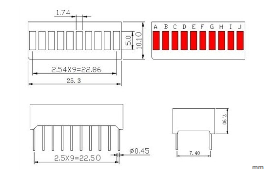
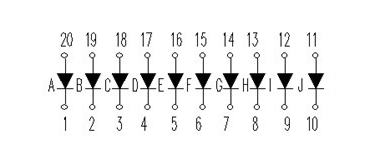
The internal schematic diagram for the LED bar graph is as shown below:
A potentiometer, informally a pot, is a three-terminal resistor with a sliding or rotating contact that forms an adjustable voltage divider. If only two terminals are used, one end and the wiper, it acts as a variable resistor or rheostat.
Procedures
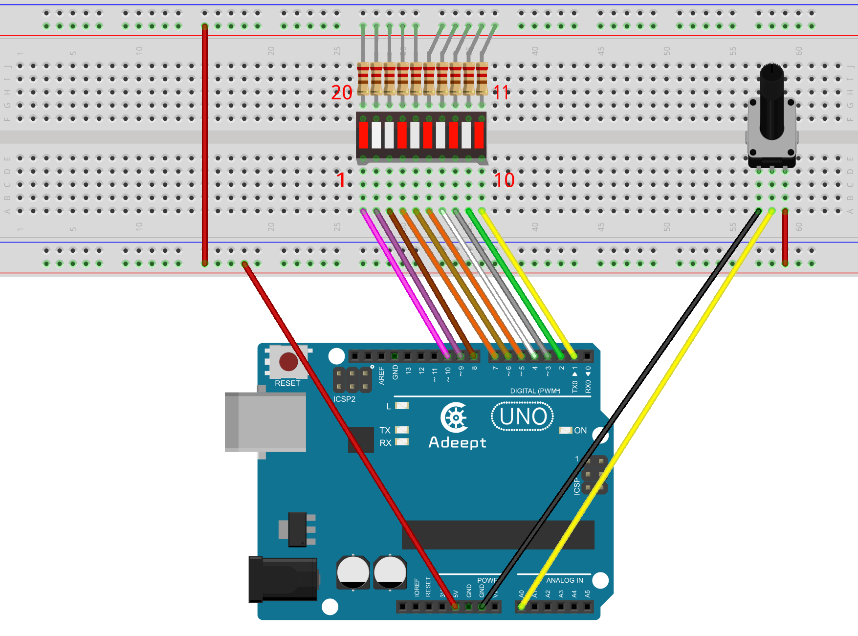
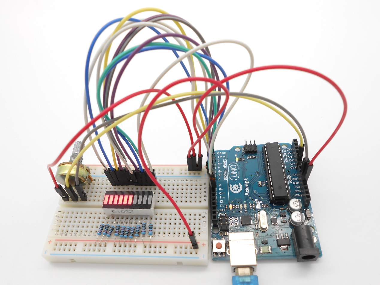
Step 1: Build the circuit
Step 2: Program
/***********************************************************
File name: 07_LEDBarGraph.ino
Description: When you turn the potentiometer you will see
             LED bar graph display changing.
Website: www.adeept.com
E-mail: support@adeept.com
Author: Tom
Date: 2015/05/02
***********************************************************/
int pin1 = 1;
int pin2 = 2;
int pin3 = 3;
int pin4 = 4;
int pin5 = 5;
int pin6 = 6;
int pin7 = 7;
int pin8 = 8;
int pin9 = 9;
int pin10 = 10;           //definition digital 10 pins as pin to control the LED

int potentiometerPin = 0; // potentiometer connected to analog pin 3

void setup()
{
  pinMode(pin1,OUTPUT);    //Set the digital 1 port mode, OUTPUT: Output mode
  pinMode(pin2,OUTPUT);    //Set the digital 2 port mode, OUTPUT: Output mode
  pinMode(pin3,OUTPUT);    //Set the digital 3 port mode, OUTPUT: Output mode
  pinMode(pin4,OUTPUT);    //Set the digital 4 port mode, OUTPUT: Output mode
  pinMode(pin5,OUTPUT);    //Set the digital 5 port mode, OUTPUT: Output mode
  pinMode(pin6,OUTPUT);    //Set the digital 6 port mode, OUTPUT: Output mode
  pinMode(pin7,OUTPUT);    //Set the digital 7 port mode, OUTPUT: Output mode
  pinMode(pin8,OUTPUT);    //Set the digital 8 port mode, OUTPUT: Output mode
  pinMode(pin9,OUTPUT);    //Set the digital 9 port mode, OUTPUT: Output mode
  pinMode(pin10,OUTPUT);    //Set the digital 10 port mode, OUTPUT: Output mode
}

void loop()
{
   float a = analogRead(potentiometerPin);//Read the voltage photoresistance
   a = map(a,0,1023,0,11);    //Photoresistor voltage value converted from 0-1023 to 0-11
   for(int i=1;i<=a;i++){
      digitalWrite(i,LOW);    //HIGH is set to about 5V PIN8
   }
   for(int j=10;j>a;j--){
      digitalWrite(j,HIGH);   //HIGH is set to about 5V PIN8
   }
   delay(50);                 //delay 50ms
}
Step 3: Compile the program and upload to Arduino UNO board
Now, turn the knob of the potentiometer, and you will see the number of LEDs in the LED bar graph changed.