Overview
In this lesson, we will learn how to use ADXL345 to collect acceleration data by programming Arduino UNO, and then display the data ADXL345 collects on the LCD1602.
Components
- 1 * Arduino UNO
- 1 * USB Cable
- 1 * LCD1602
- 1 * 10kΩ Potentiometer
- 1 * ADXL345 Acceleration Sensor
- 1 * Breadboard
- Several jumper wires
Principle
1. ADXL345
The ADXL345 is a small, thin, ultralow power, 3-axis accelerometer with high resolution (13-bit) measurement at up to ±16 g. Digital output data is formatted as 16-bit twos complement and is accessible through either a SPI (3-wire or 4-wire) or I2C digital interface. The ADXL345 is well suited for mobile device applications. It measures the static acceleration of gravity in tilt-sensing applications, as well as dynamic acceleration resulting from motion or shock. Its high resolution (3.9 mg/LSB) enables measurement of inclination changes less than 1.0°.
Low power modes enable intelligent motion-based power management with threshold sensing and active acceleration measurement at extremely low power dissipation.
2. Wire Library
This library allows you to communicate with I2C/TWI devices. I2C/TWI pins are A4 (SDA) and A5(SCL) on Arduino UNO R3 board.
3. Key functions:
●Wire.begin()
●Wire.begin(address)
Initiate the Wire library and join the I2C bus as a master or slave. This should normally be called only once.
Parameters:
address: the 7-bit slave address (optional); if not specified, join the bus as a master.
Returns:
None
●Wire.beginTransmission(address)
Begin a transmission to the I2C slave device with the given address. Subsequently, queue bytes for transmission with the write() function and transmit them by calling endTransmission().
Parameters:
address: the 7-bit address of the device to transmit to
Returns:
None
●Wire.write()
Writes data from a slave device in response to a request from a master, or queues bytes for transmission from a master to slave device (in-between calls to beginTransmission() and endTransmission()).
Syntax:
Wire.write(value)
Wire.write(string)
Wire.write(data, length)
Parameters:
value: a value to send as a single byte
string: a string to send as a series of bytes
data: an array of data to send as bytes
length: the number of bytes to transmit
Returns:
byte: write() will return the number of bytes written, though reading that number is optional
●Wire.endTransmission()
Ends a transmission to a slave device that was begun by beginTransmission() and transmits the bytes that were queued by write().
As of Arduino 1.0.1, endTransmission() accepts a boolean argument changing its behavior for compatibility with certain I2C devices.
If true, endTransmission() sends a stop message after transmission, releasing the I2C bus.
If false, endTransmission() sends a restart message after transmission. The bus will not be released, which prevents another master device from transmitting between messages. This allows one master device to send multiple transmissions while in control.
The default value is true.
Syntax:
Wire.endTransmission()
Wire.endTransmission(stop)
Parameters:
stop: boolean. true will send a stop message, releasing the bus after transmission. false will send a restart, keeping the connection active.
Returns:
byte, which indicates the status of the transmission:
-0: success
-1: data too long to fit in transmit buffer
-2: received NACK on transmit of address
-3: received NACK on transmit of data
-4: other error
●Wire.requestFrom()
Used by the master to request bytes from a slave device. The bytes may then be retrieved with the available() and read() functions.
As of Arduino 1.0.1, requestFrom() accepts a boolean argument changing its behavior for compatibility with certain I2C devices.
If true, requestFrom() sends a stop message after the request, releasing the I2C bus.
If false, requestFrom() sends a restart message after the request. The bus will not be released, which prevents another master device from requesting between messages. This allows one master device to send multiple requests while in control.
The default value is true.
Syntax:
Wire.requestFrom(address, quantity)
Wire.requestFrom(address, quantity, stop)
Parameters:
address: the 7-bit address of the device to request bytes from
quantity: the number of bytes to request
stop: boolean. true will send a stop message after the request, releasing the bus. false will continually send a restart after the request, keeping the connection active.
Returns:
byte : the number of bytes returned from the slave device
●Wire.available()
Returns the number of bytes available for retrieval with read(). This should be called on a master device after a call to requestFrom() or on a slave inside the onReceive() handler.
available() inherits from the Stream utility class.
Parameters:
None
Returns:
The number of bytes available for reading.
●Wire.read()
Reads a byte that was transmitted from a slave device to a master after a call to requestFrom() or was transmitted from a master to a slave. read() inherits from the Stream utility class.
Syntax:
Wire.read()
Parameters:
none
Returns:
The next byte received
●lcd.setCursor()
Position the LCD cursor; that is, set the location at which subsequent text written to the LCD will be displayed.
Syntax:
lcd.setCursor(col, row)
Parameters:
lcd: a variable of type LiquidCrystal
col: the column at which to position the cursor (with 0 being the first column)
row: the row at which to position the cursor (with 0 being the first row)
Procedures
Step 1: Build the circuit
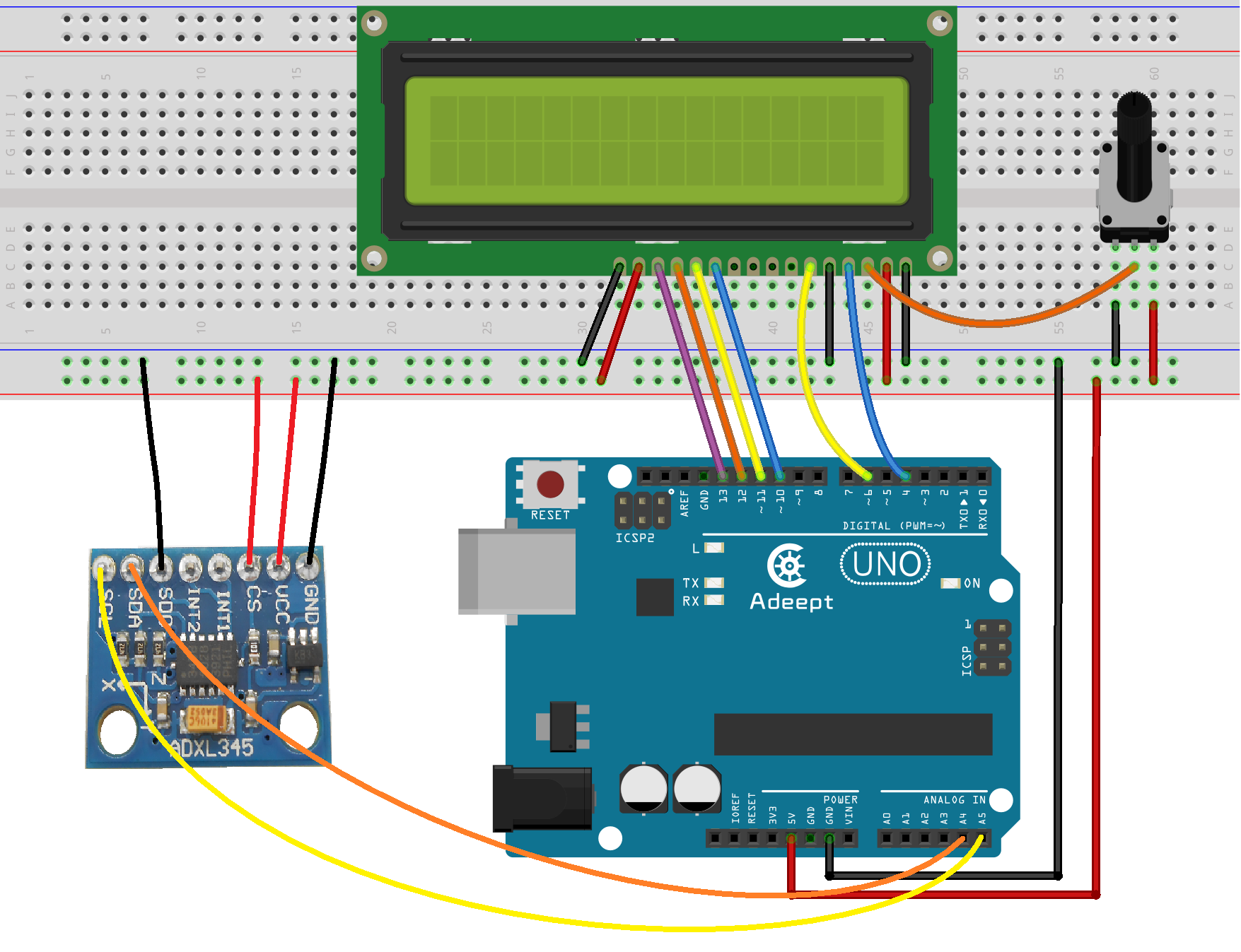
Step 2: Program
/***********************************************************
File name: 20_ADXL345.ino
Description: you can see the acceleration data which ADXL345
collected displayed on the LCD1602.
Website: www.adeept.com
E-mail: support@adeept.com
Author: Tom
Date: 2015/05/02
***********************************************************/
#include <Wire.h> //arduino IDE contains I2C library
#include <LiquidCrystal.h>
#define Register_ID 0 //Address defined ADXL345 register
#define Register_2D 0x2D
#define Register_X0 0x32
#define Register_X1 0x33
#define Register_Y0 0x34
#define Register_Y1 0x35
#define Register_Z0 0x36
#define Register_Z1 0x37
#define Reg_OFSX 0x1E //ADXL345 correct register address definitions
#define Reg_OFSY 0x1F
#define Reg_OFSZ 0x20
#define Reg_PWR_CTL 0x2D
LiquidCrystal lcd(4, 6, 10, 11, 12, 13);
int ADXAddress = 0xA7>>1; //Converted to 7 address
int reading = 0;
int val = 0;
int X0,X1,X_out;
int Y0,Y1,Y_out;
int Z1,Z0,Z_out;
double Xg,Yg,Zg;
void setup()
{
lcd.begin(16, 2); // set up the LCD's number of columns and rows:
lcd.clear(); //Clears the LCD screen and positions the cursor in the upper-left corner
delay(100);
Wire.begin(); //Initializes I2C
setAccReg(0x31,0x0B); //Measuring range, plus or minus 16g, 13 bit pattern
setAccReg(0x2C,0x08); //Reference rate is set to 12.5 Page pdf13
setAccReg(0x2D,0x08); //Select Power Mode Reference pdf24 page
setAccReg(0x2E,0x80); //Interrupt Enable DATA_READY
setAccReg(0x1E,0x00); //X Offset pdf29 page written test based on the state of the sensor
setAccReg(0x1F,0x00); //Y offset pdf29 page written test based on the state of the sensor
setAccReg(0x20,0x05); //Z offset pdf29 page written test based on the state of the sensor
delay(100);
Wire.beginTransmission(ADXAddress);
Wire.write(Register_2D);
Wire.write(8);
Wire.endTransmission();
delay(500);
}
void loop()
{
Wire.beginTransmission(ADXAddress);//Read X-axis data
Wire.write(Register_X0);
Wire.write(Register_X1);
Wire.endTransmission();
Wire.requestFrom(ADXAddress,2);
if(Wire.available()<=2)
{
X0 = Wire.read();
X1 = Wire.read();
X1 = X1<<8;
X_out = X0+X1;
}
Wire.beginTransmission(ADXAddress);//Read y-axis data
Wire.write(Register_Y0);
Wire.write(Register_Y1);
Wire.endTransmission();
Wire.requestFrom(ADXAddress,2);
if(Wire.available()<=2)
{
Y0 = Wire.read();
Y1 = Wire.read();
Y1 = Y1<<8;
Y_out = Y0+Y1;
}
Wire.beginTransmission(ADXAddress);//Read z-axis data
Wire.write(Register_Z0);
Wire.write(Register_Z1);
Wire.endTransmission();
Wire.requestFrom(ADXAddress,2);
if(Wire.available()<=2)
{
Z0 = Wire.read();
Z1 = Wire.read();
Z1 = Z1<<8;
Z_out = Z0+Z1;
}
Xg = X_out/256.00; //The output is converted to gravitational acceleration g, 2 decimal places later.
Yg = Y_out/256.00;
Zg = Z_out/256.00;
lcd.clear(); //Clear screen
lcd.setCursor(0, 0); //set the cursor to column 0, line 0
lcd.print("Adeept X="); //So that the display text 'Adeept X ='
lcd.print(Xg);
lcd.setCursor(0, 1); // set the cursor to column 0, line 1
lcd.print("Y=");
lcd.print(Yg);
lcd.setCursor(8, 1); // set the cursor to column 8, line 1
lcd.print("Z=");
lcd.print(Zg);
delay(300); //Delay 0.3 seconds, the refresh rate is adjusted here
}
void setAccReg(int reg,byte value){
setReg(ADXAddress,reg,value); //ADXAddress = 0xA7>>1
}
void setReg(int device,int reg,byte value){
Wire.beginTransmission(device);
Wire.write(reg);
Wire.write(value);
Wire.endTransmission();
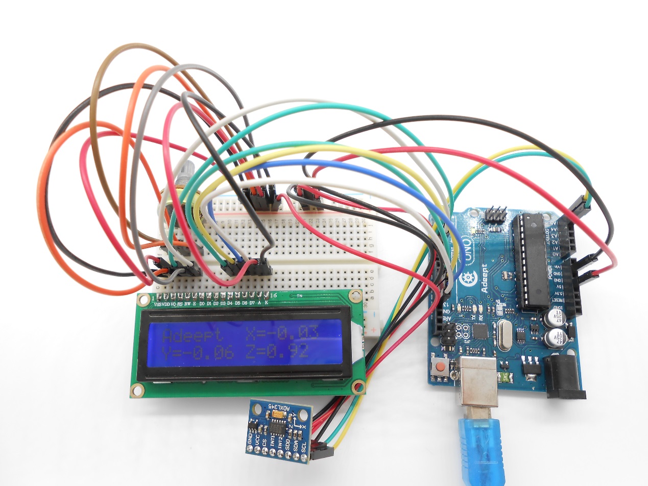
}Step 3: Compile the program and upload to Arduino UNO board
Now, you can see the acceleration data collected by ADXL345 displayed on the LCD1602.
Summary
After learning this lesson, you should have got the usage of the ADXL345. Next, you can use it to make more interesting applications.