Overview
In this lesson, we will learn how to control a relay to break or connect a circuit.
Components
- 1 * Arduino UNO
- 1 * USB Cable
- 1 * NPN Transistor (S8050)
- 1 * 1K Resistor
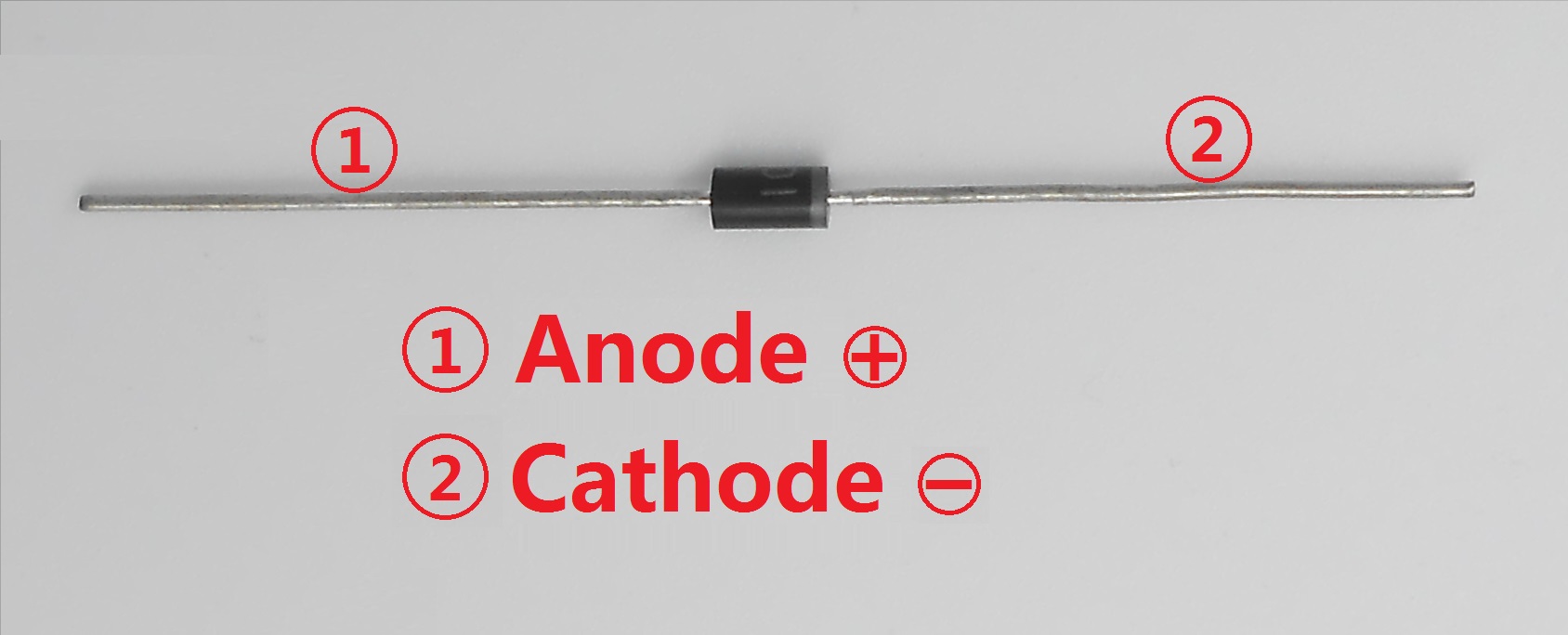
- 1 * 1N4001 Diode
- 1 * 220Ω Resistor
- 1 * Relay
- 1 * LED
- 1 * Breadboard
- Several jumper wires
Principle
A relay is an electrically operated switch. It is generally used in automatic control circuit. Actually, it is an "automatic switch" which uses low current to control high current. It plays a role of automatic regulation, security protection and circuit switch. When an electric current is passed through the coil it generates a magnetic field that activates the armature, and the consequent movement of the movable contact (s) either makes or breaks (depending upon construction) a connection with a fixed contact. If the set of contacts was closed when the relay was de-energized, then the movement opens the contacts and breaks the connection, and vice versa if the contacts were open. When the current to the coil is switched off, the armature is returned by a force, approximately half as strong as the magnetic force, to its relaxed position. Usually this force is provided by a spring, but gravity is also used commonly in industrial motor starters. Most relays are manufactured to operate quickly. In a low-voltage application this reduces noise; in a high voltage or current application it reduces arcing.
When the coil is energized with direct current, a diode is often placed across the coil to dissipate the energy from the collapsing magnetic field at deactivation, which would otherwise generate a voltage spike dangerous to semiconductor circuit components.
Procedures
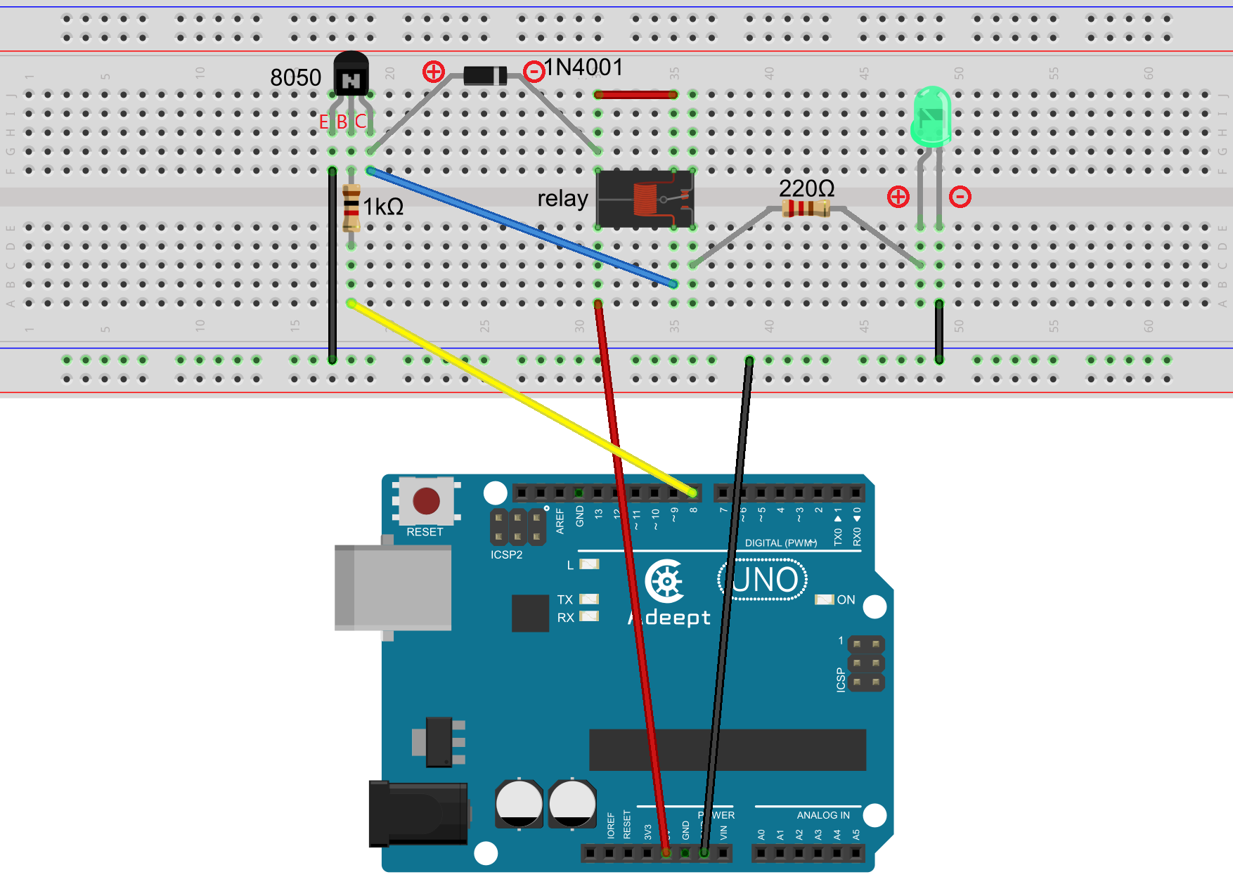
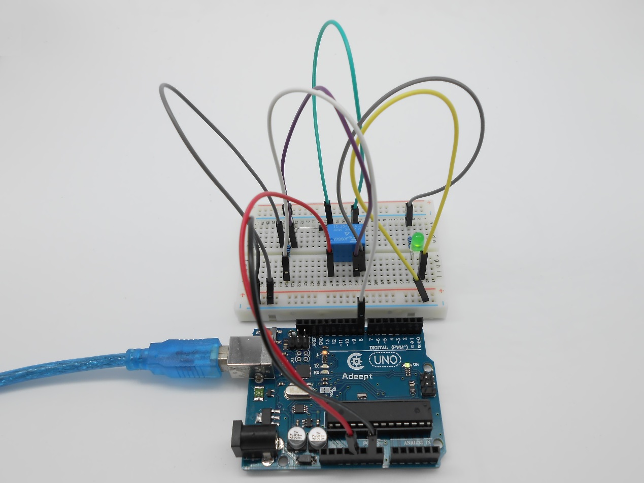
Step 1: Build the circuit
Step 2: Program
/***********************************************************
File name: 04_relay.ino
Description:When the relay sucks, the LED will light up; when
            the relay breaks, the LED will go out.
Website: www.adeept.com
E-mail: support@adeept.com
Author: Tom
Date: 2015/05/05
***********************************************************/
const int relayPin = 8; //the base of the transistor attach to

void setup()
{
  pinMode(relayPin, OUTPUT); //initialize the relayPin as an output
}

void loop()
{
  digitalWrite(relayPin, HIGH); //drive relay closure conduction
  delay(1000); //wait for a second

  digitalWrite(relayPin, LOW); //drive the relay is closed off
  delay(1000); //wait for a second
}
Step 3: Compile the program and upload to Arduino UNO board
Now let's see what will happen: When the set of contacts are closed, the LED lights up; when they are open, the LED goes out.
Summary
By this lesson, you should have learned the basic principle of relay. You can also use the relay to do some creative applications. Just give it a try!