Overview
In this lesson, we will make a simple frequency meter with the Arduino UNO. We will acquire the frequency of square wave which is generated by 555 timer, and then send the result to serial monitor through USB port.
Components
- 1 * Arduino UNO
- 1 * USB Cable
- 1 * NE555 Timer
- 1 * 10kΩ Resistor
- 1 * 10kΩ Potentiometer
- 2 * 104 Capacitor
- 1 * Breadboard
- Several jumper wires
Principle
1. NE555
The 555 integrated circuit is originally used as a timer, and that is why it is called 555 timer or 555 time-based circuit. It is widely used in various electronic products because of its reliability, convenience and low price. There are dozens of components in the 555 integrated circuit, such as divider, comparator, basic R-S trigger, discharge tube, and buffer. This is a complex circuit and a hybrid composed of analog and digital circuits.
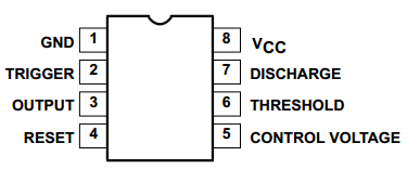
As shown in the above figure, the 555 integrated circuit is dual in-line with 8 pins package(DIP).
Pin 6 is the THRESHOLD for the input of upper comparator;
Pin 2 is TRIGGER for the input of lower comparator;
Pin 3 is the OUTPUT having two states of 0 and 1 decided by the input electrical level;
Pin 7, the DISCHARGE which has two states of suspension and ground connection also decided by input, is the output of the internal discharge tube;
Pin 4 is the RESET that outputs low level when supplied low voltage level;
Pin 5 is the CONTROL VOLTAGE that can change the upper and lower level trigger value;
Pin 8 (Vcc) is the power supply;
Pin 1(GND) is the ground.
The schematic diagram used in the experiment is as shown below:
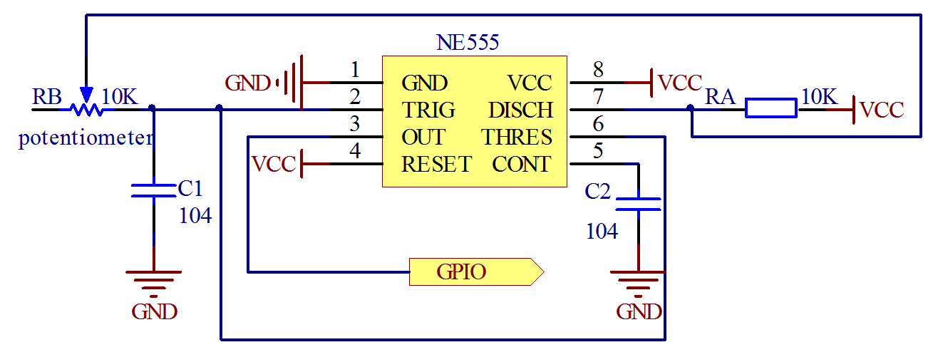
The circuit can generate a square wave signal that the frequency is adjustable. The frequency can be calculated by the formula:
![F]~]$[6SSBOJ3O0ER}4[]@I.png](/upload/learn/image/20190819/1566208920463243.png)
2. Key functions:
●pulseIn()
Reads a pulse (either HIGH or LOW) on a pin. For example, if value is HIGH, pulseIn() waits for the pin to go HIGH, starts timing, then waits for the pin to go LOW and stops timing. Returns the length of the pulse in microseconds. Gives up and returns 0 if no pulse starts within a specified time out.
The timing of this function has been determined empirically and will probably show errors in longer pulses. Works on pulses from 10 microseconds to 3 minutes in length.
Syntax:
pulseIn(pin, value)
pulseIn(pin, value, timeout)
Parameters:
pin: the number of the pin on which you want to read the pulse. (int)
value: type of pulse to read: either HIGH or LOW. (int)
timeout (optional): the number of microseconds to wait for the pulse to start; default is one second (unsigned long)
Returns:
the length of the pulse (in microseconds) or 0 if no pulse started before the timeout (unsigned long)
Procedures
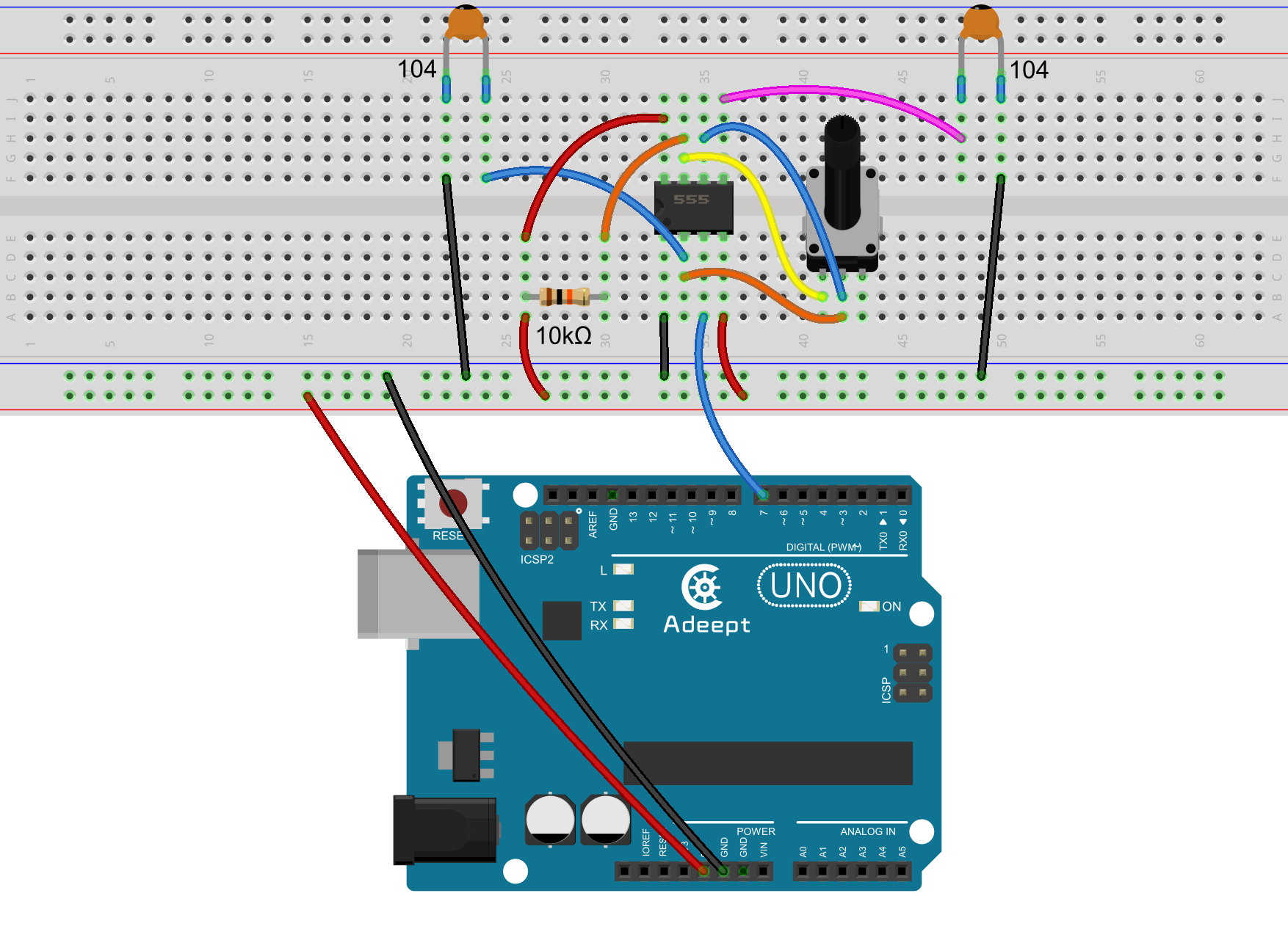
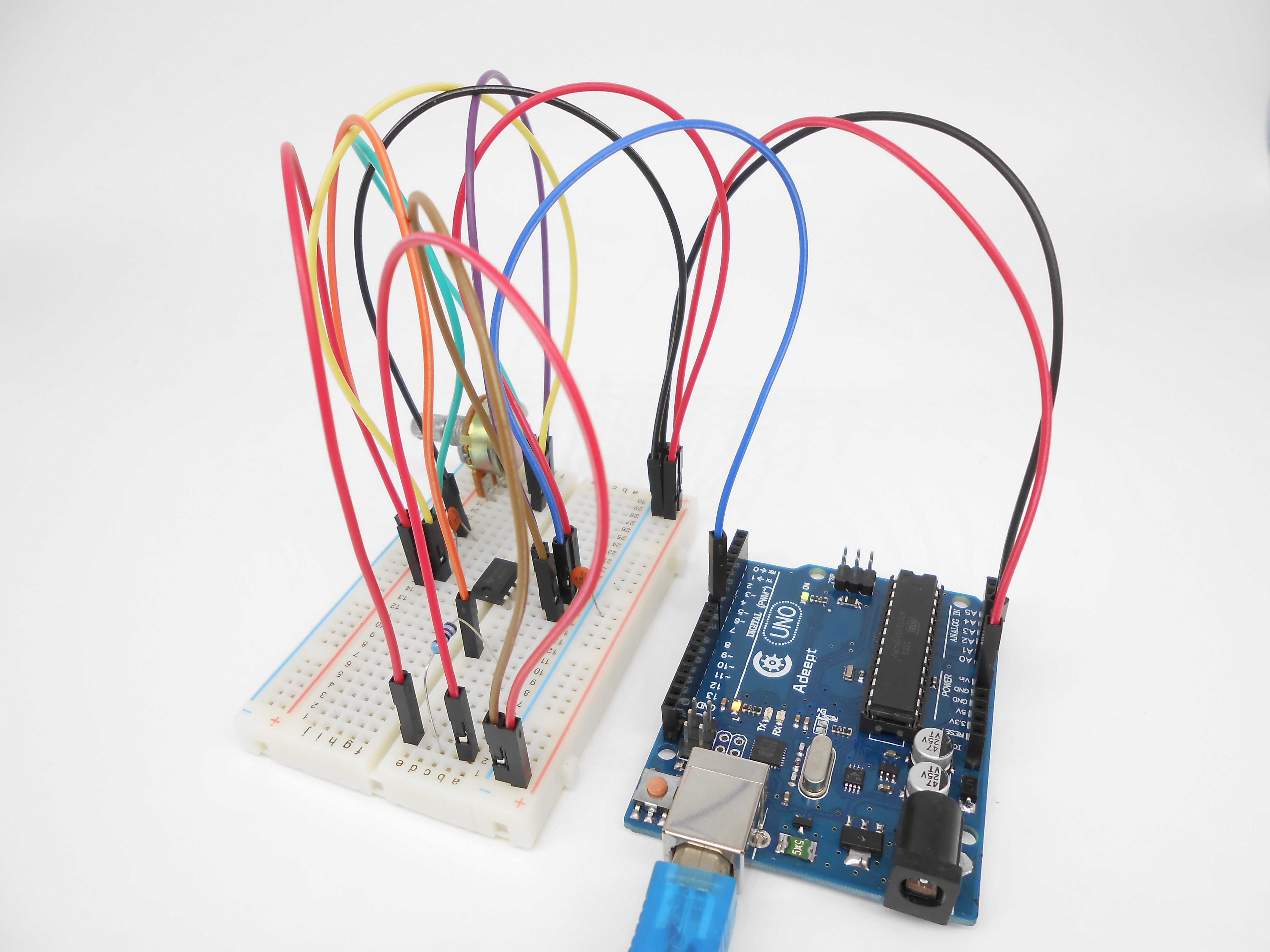
Step 1: Build the circuit (Make sure that the circuit connection is correct before powering on; otherwise it may cause the chips to burn.)
Step 2: Program
/***********************************************************
File name: 29_timer555.ino
Description: Use Arduino UNO gathering issued NE555 square wave.
Square wave frequency values were collected via a
serial port will be sent to the serial monitor display.
Website: www.adeept.com
E-mail: support@adeept.com
Author: Tom
Date: 2015/05/02
***********************************************************/
int pin = 7; //attach to the third pin of NE555
unsigned long duration; //the variable to store the length of the pulse
unsigned long durationhigh;//the variable to store the length of the pulse
unsigned long durationlow; //the variable to store the length of the pulse
void setup()
{
pinMode(pin, INPUT); //set the pin as an input
Serial.begin(9600); // start serial port at 9600 bps:
}
void loop()
{
durationhigh = pulseIn(pin, HIGH); //Reads a pulse on pin
durationlow = pulseIn(pin, LOW); //Reads a pulse on pin
duration = 1000000/(durationhigh + durationlow);
Serial.print("Freq: "); //print Freq:
Serial.print(duration); //print the length of the pulse on the serial monitor
Serial.print("Hz HTime: "); //print Hz HTime:
Serial.print(durationhigh); //print the length of the pulse on the serial monitor
Serial.print("us LTime: "); //print us LTime:
Serial.print(durationlow); //print the length of the pulse on the serial monitor
Serial.print("us "); //print us
Serial.println(); //print an blank on serial monitor
delay(500); //wait for 500 microseconds
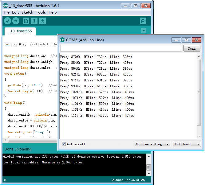
}Step 3: Compile the program and upload to Arduino UNO board
Now, rotate the potentiometer knob, and the frequency value of square waves printed on Serial Monitor will be changed.
Summary
Afrer this lesson, you should have mastered the principle of timer and can make a simple frequency meter by yourself. You can display the value of square frequency to a LCD1602 by modifying the code we provided.