Overview
In this lesson, we will program the Arduino UNO to make a simple counter.
Components
- 1 * Arduino UNO
- 1 * USB Cable
- 1 * 4-digit 7-segment Display
- 8 * 220Ω Resistor
- 2 * Button
- 1 * Breadboard
- Several jumper wires
Principle
The 4-digit segment display is a form of electronic display device for displaying decimal numerals that is an alternative to the more complex dot matrix displays.
4-digit segment displays are widely used in digital clocks, electronic meters, basic calculators, and other electronic devices that display numerical information.
The 4-digit segment display is a 4*8-shaped LED display device composed of 32 LEDs (including four decimal points). The segments arenamed respectively a, b, c, d, e, f, g, h, dig1, dig2, dig3, and dig4.
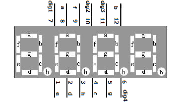
What we use in this experiment is a common cathode 4-digit 7-segment display. Its internal structure is as shown below:
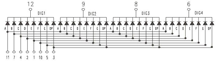
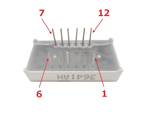
The pin number is as follows:
Procedures
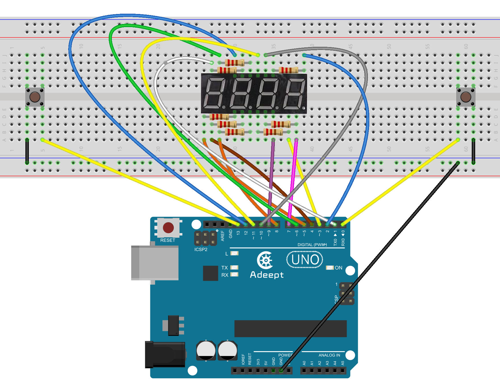
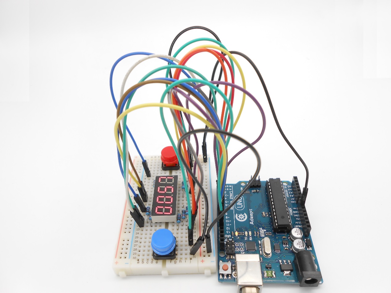
Step 1: Build the circuit
Step 2: Program
/***********************************************************
File name: 14_aSimpleCounter.ino
Description:when you are pressing two buttons, four-digit
            segment display values will change.
Website: www.adeept.com
E-mail: support@adeept.com
Author: Tom
Date: 2015/05/05
***********************************************************/
int btn1pin=0;             //Set the digital 0 to button interface
int btn2pin=13;            //Set the digital 13 to button interface
int a = 1;
int b = 2;
int c = 3;
int d = 4;
int e = 5;
int f = 6;
int g = 7;
int p = 8;
int d4 = 9;
int d3 = 10;
int d2 = 11;
int d1 = 12;

long n = 0;
int x = 100;
int del = 55;
int i = 0;
int j = 1;
int k = 2;
int l = 3;
int data;
void setup()
{
  pinMode(btn1pin,INPUT_PULLUP); //Set digital 2 port mode, the INPUT for the input
  pinMode(btn2pin,INPUT_PULLUP); //Set digital 2 port mode, the INPUT for the input
  pinMode(d1, OUTPUT);
  pinMode(d2, OUTPUT);
  pinMode(d3, OUTPUT);
  pinMode(d4, OUTPUT);
  pinMode(a, OUTPUT);
  pinMode(b, OUTPUT);
  pinMode(c, OUTPUT);
  pinMode(d, OUTPUT);
  pinMode(e, OUTPUT);
  pinMode(f, OUTPUT);
  pinMode(g, OUTPUT);
  pinMode(p, OUTPUT);
}

void loop()
{
  int d1,d2,d3,d4;
  if(digitalRead(btn1pin)==LOW)          //Detection button interface to low
  {
      delay(10);                         //Delay 10ms for the elimination of key leading-edge jitter
      if(digitalRead(btn1pin)==LOW)      //Confirm button is pressed
      {
        if(data>9999)
        {
          data=9999;
        }else{
          data = data + 1;
        }
      }
   }
   if(digitalRead(btn2pin)==LOW)          //Detection button interface to low
  {
      delay(10);                        //Delay 10ms for the elimination of key leading-edge jitter
      if(digitalRead(btn2pin)==LOW)      //Confirm button is pressed
      {
        if(data<=0)
        {
          data=0;
        }else{
          data = data - 1;
        }
      }
   }
   d1 = data/1000%10;    //The one thousand digital data
   d2 = data/100%10;     //The one hundred digital data
   d3 = data/10%10;      //Ten-digit data
   d4 = data%10;         //data of single digit
  for(int m=0;m<80;m++){
  clearLEDs();           //Turn off all LED lights
  pickDigit(1);          //Selection of a digital display
  pickNumber(d1);        //Display digital d1
  delayMicroseconds(200);

  clearLEDs();           //Turn off all LED lights
  pickDigit(2);          //Select the first two digital display
  pickNumber(d2);        //Display digital d2
  delayMicroseconds(200);

  clearLEDs();           //Turn off all LED lights
  pickDigit(3);          //Select the first three digital display
  //dispDec(3);          //Decimal display
  pickNumber(d3);        //Display digital d3
  delayMicroseconds(200);

  clearLEDs();           //Turn off all LED lights
  pickDigit(4);          //Select the first four digital display
  pickNumber(d4);        //Display digital d4
  delayMicroseconds(200);
  }
}

void pickDigit(int x)  //Defined pickDigit (x), whose role is to open the port dx
{
  digitalWrite(d1, HIGH);
  digitalWrite(d2, HIGH);
  digitalWrite(d3, HIGH);
  digitalWrite(d4, HIGH);
  switch(x)
  {
    case 1:
           digitalWrite(d1, LOW);
           break;
    case 2:
           digitalWrite(d2, LOW);
           break;
    case 3:
           digitalWrite(d3, LOW);
           break;
    default:
           digitalWrite(d4, LOW);
           break;
  }
}

void pickNumber(int x)   //Defined pickNumber (x), whose role is to display digital x
{
  switch(x)
  {
    case 1:
           one();
           break;
    case 2:
           two();
           break;
    case 3:
           three();
           break;
    case 4:
           four();
           break;
    case 5:
           five();
           break;
    case 6:
           six();
           break;
    case 7:
	   seven();
	   break;
    case 8:
	   eight();
	   break;
    case 9:
	   nine();
	   break;
    default:
           zero();
           break;
  }
}

void dispDec(int x)  //Decimal point setting Open
{
  digitalWrite(p, HIGH);
}

void clearLEDs()  //Clear screen
{
  digitalWrite(a, LOW);
  digitalWrite(b, LOW);
  digitalWrite(c, LOW);
  digitalWrite(d, LOW);
  digitalWrite(e, LOW);
  digitalWrite(f, LOW);
  digitalWrite(g, LOW);
  digitalWrite(p, LOW);
}

void zero()  //Define those figures 0 cathode pin switch
{
  digitalWrite(a, HIGH);
  digitalWrite(b, HIGH);
  digitalWrite(c, HIGH);
  digitalWrite(d, HIGH);
  digitalWrite(e, HIGH);
  digitalWrite(f, HIGH);
  digitalWrite(g, LOW);
}

void one()  //Define those figures 1 cathode pin switch
{
  digitalWrite(a, LOW);
  digitalWrite(b, HIGH);
  digitalWrite(c, HIGH);
  digitalWrite(d, LOW);
  digitalWrite(e, LOW);
  digitalWrite(f, LOW);
  digitalWrite(g, LOW);
}

void two()  //Define those figures 2 cathode pin switch
{
  digitalWrite(a, HIGH);
  digitalWrite(b, HIGH);
  digitalWrite(c, LOW);
  digitalWrite(d, HIGH);
  digitalWrite(e, HIGH);
  digitalWrite(f, LOW);
  digitalWrite(g, HIGH);
}

void three()  //Define those figures 3 cathode pin switch
{
  digitalWrite(a, HIGH);
  digitalWrite(b, HIGH);
  digitalWrite(c, HIGH);
  digitalWrite(d, HIGH);
  digitalWrite(e, LOW);
  digitalWrite(f, LOW);
  digitalWrite(g, HIGH);
}

void four()  //Define those figures 4 cathode pin switch
{
  digitalWrite(a, LOW);
  digitalWrite(b, HIGH);
  digitalWrite(c, HIGH);
  digitalWrite(d, LOW);
  digitalWrite(e, LOW);
  digitalWrite(f, HIGH);
  digitalWrite(g, HIGH);
}

void five()  //Define those figures 5 cathode pin switch
{
  digitalWrite(a, HIGH);
  digitalWrite(b, LOW);
  digitalWrite(c, HIGH);
  digitalWrite(d, HIGH);
  digitalWrite(e, LOW);
  digitalWrite(f, HIGH);
  digitalWrite(g, HIGH);
}

void six()  //Define those figures 6 cathode pin switch
{
  digitalWrite(a, HIGH);
  digitalWrite(b, LOW);
  digitalWrite(c, HIGH);
  digitalWrite(d, HIGH);
  digitalWrite(e, HIGH);
  digitalWrite(f, HIGH);
  digitalWrite(g, HIGH);
}

void seven()  //Define those figures 7 cathode pin switch
{
  digitalWrite(a, HIGH);
  digitalWrite(b, HIGH);
  digitalWrite(c, HIGH);
  digitalWrite(d, LOW);
  digitalWrite(e, LOW);
  digitalWrite(f, LOW);
  digitalWrite(g, LOW);
}

void eight()  //Define those figures 8 cathode pin switch
{
  digitalWrite(a, HIGH);
  digitalWrite(b, HIGH);
  digitalWrite(c, HIGH);
  digitalWrite(d, HIGH);
  digitalWrite(e, HIGH);
  digitalWrite(f, HIGH);
  digitalWrite(g, HIGH);
}

void nine()  //Define those figures 9 cathode pin switch
{
  digitalWrite(a, HIGH);
  digitalWrite(b, HIGH);
  digitalWrite(c, HIGH);
  digitalWrite(d, HIGH);
  digitalWrite(e, LOW);
  digitalWrite(f, HIGH);
  digitalWrite(g, HIGH);
}
Step 3: Compile the program and upload to Arduino UNO board
Now, press one button of the two, and the value displayed on the 4-digit 7-segment display will be changed.
Summary
By learning this lesson, you'll find that it is so easy to make a simple counter. Then, try your own ways to use this tool to impress makers!