Overview
In this lesson, we will learn how to program the Arduino to generate PWM signals. And then we use the PWM square-wave signals to control an LED gradually getting brighter and then slowly dimmer, much like human breath.
Components
- 1 * Arduino UNO
- 1 * USB Cable
- 1 * LED
- 1 * 220Ω Resistor
- 1 * Breadboard
- Several jumper wires
Principle
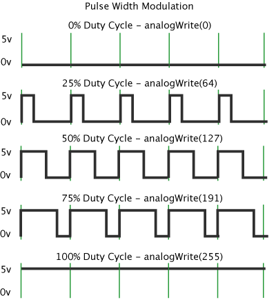
Pulse Width Modulation, or PWM, is a technique for getting analog results with digital means. Digital control is used to create a square wave, a signal switched between on and off. This on-off pattern can simulate voltages in between full on (5 Volts) and off (0 Volts) by changing the portion of the time the signal spends on versus the time that the signal spends off. The duration of "on time" is called the pulse width. To get varying analog values, you change, or modulate, that pulse width. If you repeat this on-off pattern fast enough with an LED for example, the result is as if the signal is a steady voltage between 0 and 5v controlling the brightness of the LED.
In the following figure, the green lines represent a regular time period. This duration or period is the inverse of the PWM frequency. In other words, with Arduino's PWM frequency at about 500Hz, the green lines would measure 2 milliseconds each. A call to analogWrite() is on a scale of 0 - 255, such that analogWrite(255) requests a 100% duty cycle (always on), and analogWrite(127) is a 50% duty cycle (on half the time) for example.
Key function:
●analogWrite()
Writes an analog value (PWM wave) to a pin. Can be used to light an LED at varying brightnesses or drive a motor at various speeds. After a call to analogWrite(), the pin will generate a steady square wave of the specified duty cycle until the next call to analogWrite() (or a call to digitalRead() or digitalWrite() on the same pin). You do not need to call pinMode() to set the pin as an output before calling analogWrite().
Syntax:
analogWrite(pin, value)
Parameters:
pin: the pin to write to.
value: the duty cycle: between 0 (always off) and 255 (always on).
Returns:
nothing
Procedures
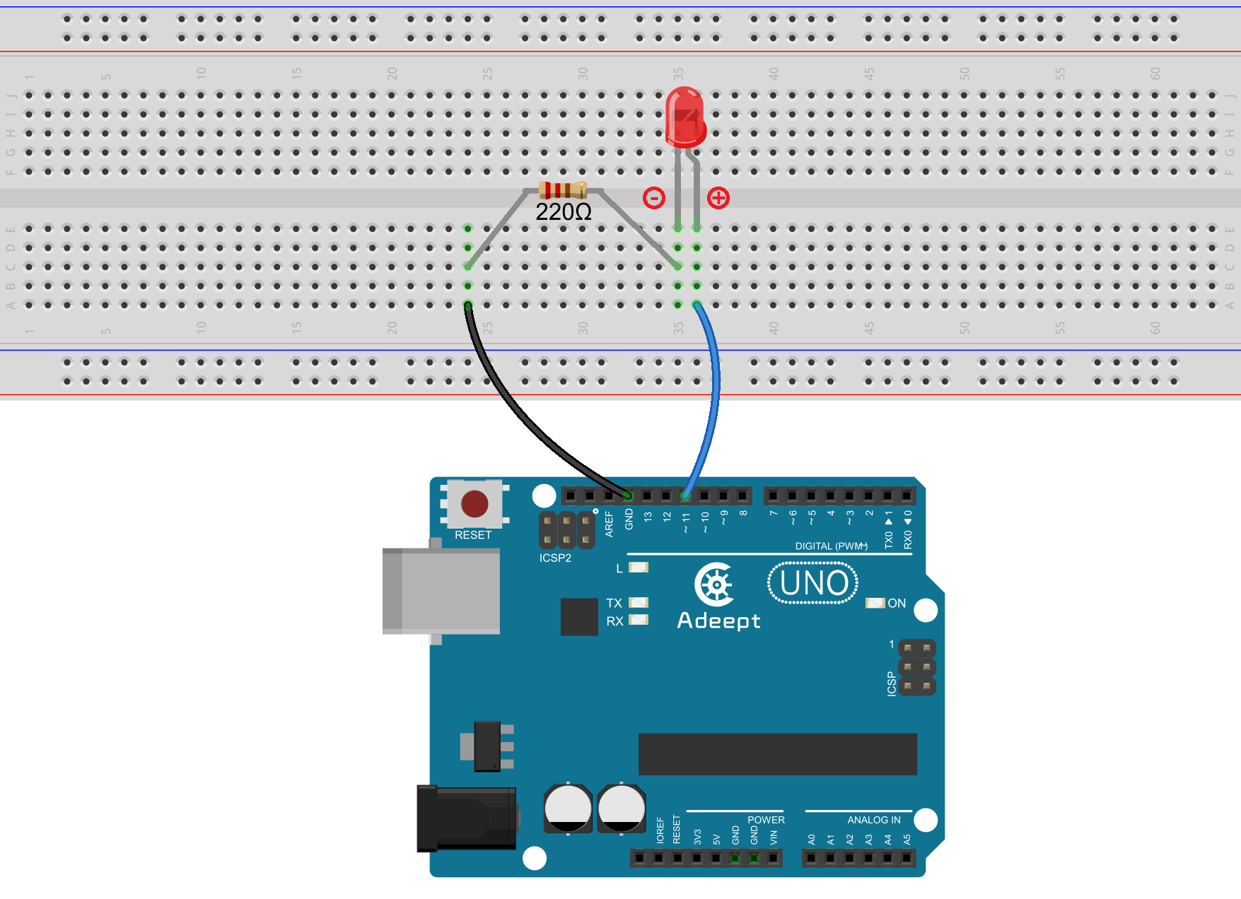
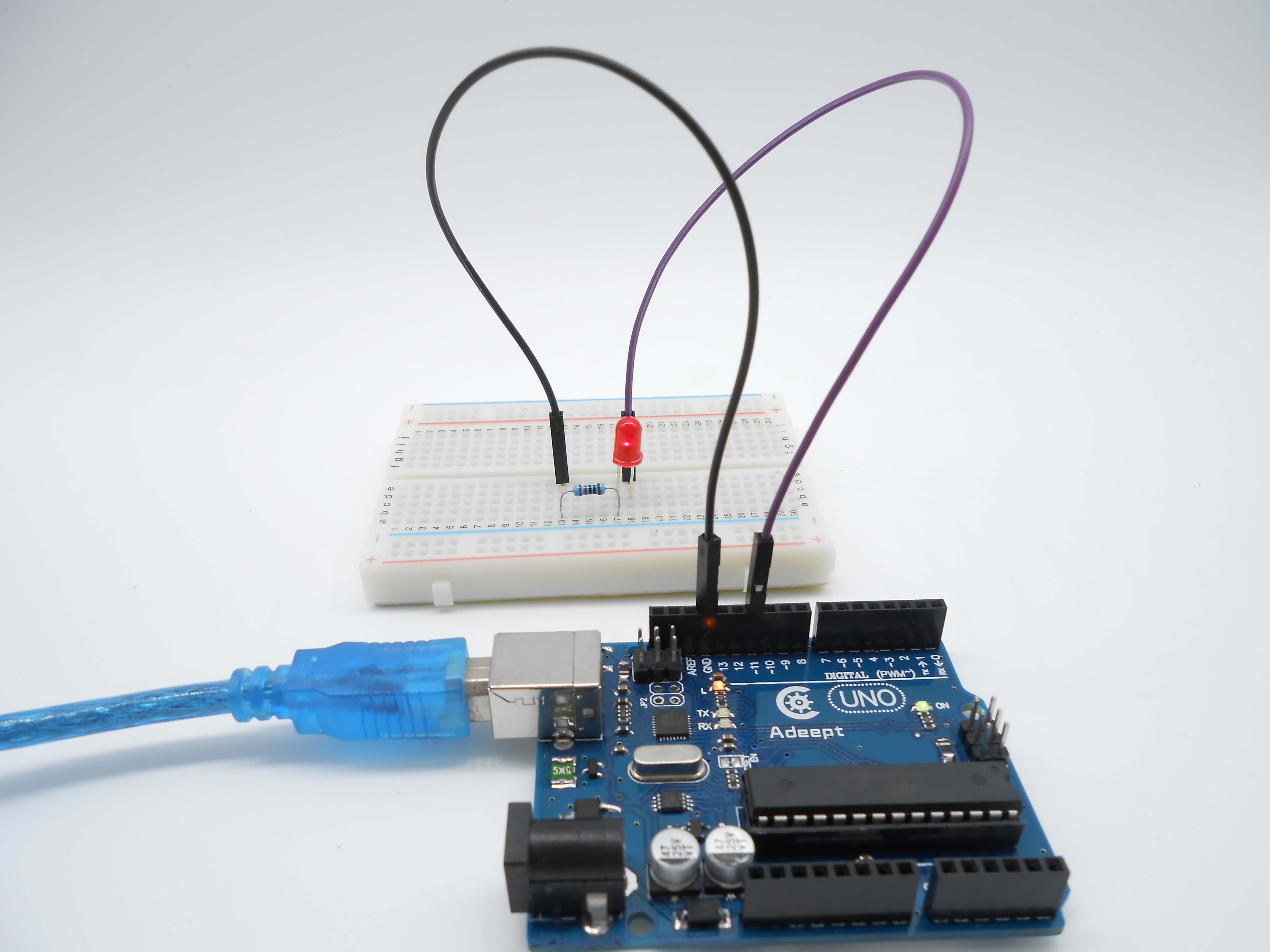
Step 1: Build the circuit
Step 2: Program
/***********************************************************
File name: 08_breathingLed.ino
Description: PWM control the LED gradually from dark to
             brighter, then from brighter to dark
Website: www.adeept.com
E-mail: support@adeept.com
Author: Tom
Date: 2015/05/02
***********************************************************/
int ledpin=11; //definition digital 11 pins as pin to control the LED

void setup ()
{
  pinMode(ledpin,OUTPUT); //Set digital 11 port mode, the OUTPUT for the output
}

void loop()
{
   for (int a=0; a<=255;a++)  //Loop, PWM control of LED brightness increase
   {
     analogWrite(ledpin,a);   //PWM output value a (0~255)
     delay(15);                //The duration of the current brightness level. 15ms
   }
   for (int a=255; a>=0;a--)  //Loop, PWM control of LED brightness Reduced
   {
     analogWrite(ledpin,a);   //PWM output value a (255~0)
     delay(15);                //The duration of the current brightness level. 15ms
   }
   delay(100);                //100ms delay
}
Step 3: Compile the program and upload to Arduino UNO board.
Now, you should see the LED lights up and gets gradually brighter, and then slowly turns dimmer. The process repeats circularly, and with the particular rhythm it looks like animals' breath.
Summary
By learning this lesson, you should have mastered the basic principles of the PWM, and get skilled at the PWM programming on the Arduino platform.