Overview
In this lesson, we will program to control a 8*8 dot-matrix to realize the display of graphical and digital we want.
Components
- 1 * Arduino UNO
- 1 * USB Cable
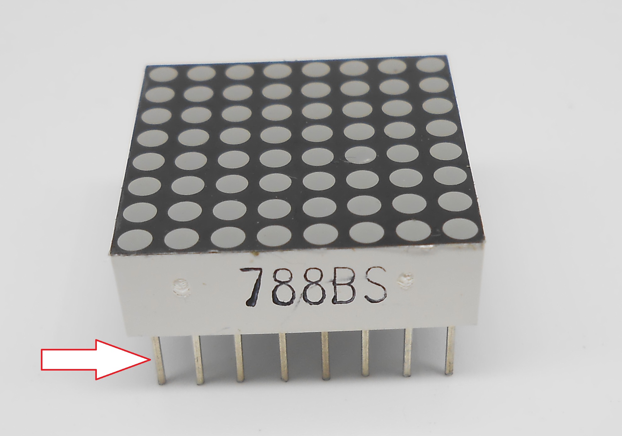
- 1 * 8*8 Dot-matrix
- 2 * 74HC595
- 1 * Breadboard
- Several jumper wires
Principle
1. Dot-matrix display
A dot-matrix display is a display device used to display information on machines, clocks, railway departure indicators and many other devices requiring a simple display device of limited resolution.
The display consists of a dot-matrix of lights or mechanical indicators arranged in a rectangular configuration (other shapes are also possible, although not common) such that by switching on or off selected lights, text or graphics can be displayed. A dot-matrix controller converts instructions from a processor into signals which turns on or off lights in the matrix so that the required display is produced.
The internal structure and appearance of the dot-matrix display is as shown in below:
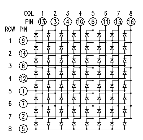
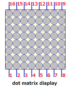
A 8*8 dot-matrix display consists of 64 LEDs, and each LED is placed at the intersection of the lines and columns. When the corresponding row is set as high level and the column is set as low level, then the LED will be lit.
A certain drive current is required for the dot-matrix display. In addition, more pins are needed for connecting dot-matrix display with controller. Thus, to save the Arduino’s GPIO, driver IC 74HC595 is used in the experiment.
2. 74HC595
The 74HC595 is an 8-stage serial shift register with a storage register and 3-state outputs. The shift register and storage register have separate clocks. Data is shifted on the positive-going transitions of the SH_CP input. The data in each register is transferred to the storage register on a positive-going transition of the ST_CP input. The shift register has a serial input (DS) and a serial standard output (![]() ) for cascading. It is also provided with asynchronous reset (active LOW) for all 8 shift register stages. The storage register has 8 parallel 3-state bus driver outputs. Data in the storage register appears at the output whenever the output enable input (OE) is LOW.
) for cascading. It is also provided with asynchronous reset (active LOW) for all 8 shift register stages. The storage register has 8 parallel 3-state bus driver outputs. Data in the storage register appears at the output whenever the output enable input (OE) is LOW.
In this experiment, only 3 pins of Arduino are used for controlling a dot-matrix display due to the existence of 74HC595.
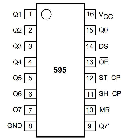
The flowing is the function of each pin:
DS: Serial data input
Q0-Q7: 8-bit parallel data output
Q7’: Series data output pin, always connected to DS pin of the next 74HC595
OE: Output enable pin, effective at low level, connected to the ground directly
MR: Reset pin, effective at low level, directly connected to 5V high level in practical applications
SH_CP: Shift register clock input
ST_CP: storage register clock input
3. Key function:
●shiftOut()
Shifts out a byte of data one bit at a time. Starts from either the most (i.e. the leftmost) or least (rightmost) significant bit. Each bit is written in turn to a data pin, after which a clock pin is pulsed (taken high, then low) to indicate that the bit is available.
Syntax:
shiftOut(dataPin, clockPin, bitOrder, value)
Parameters:
dataPin: the pin on which to output each bit (int).
clockPin: the pin to toggle once the dataPin has been set to the correct value.
bitOrder: which order to shift out the bits; either MSBFIRST or LSBFIRST. (Most Significant Bit First, or, Least Significant Bit First)
value: the data to shift out. (byte)
Returns:
None
Procedures
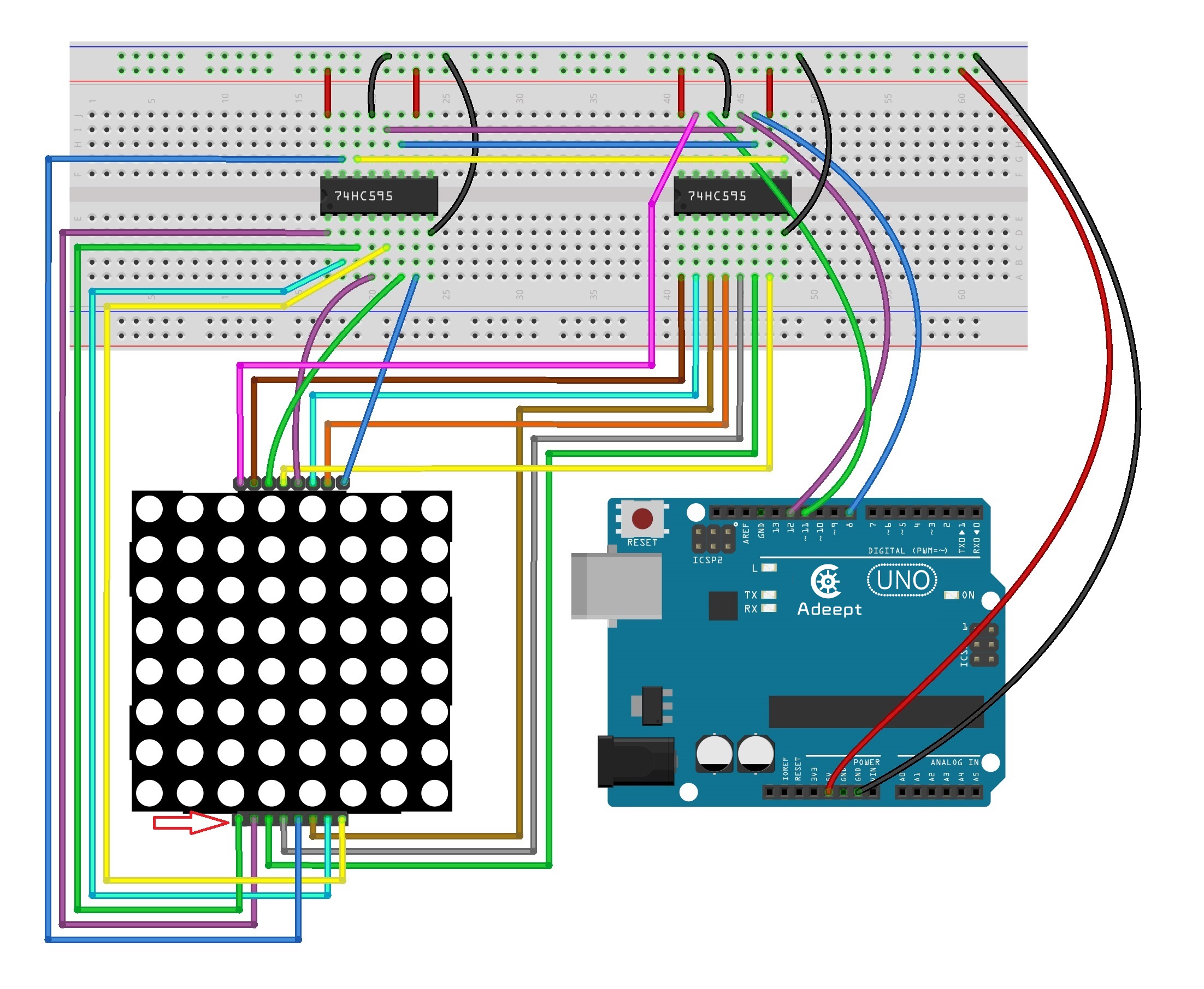
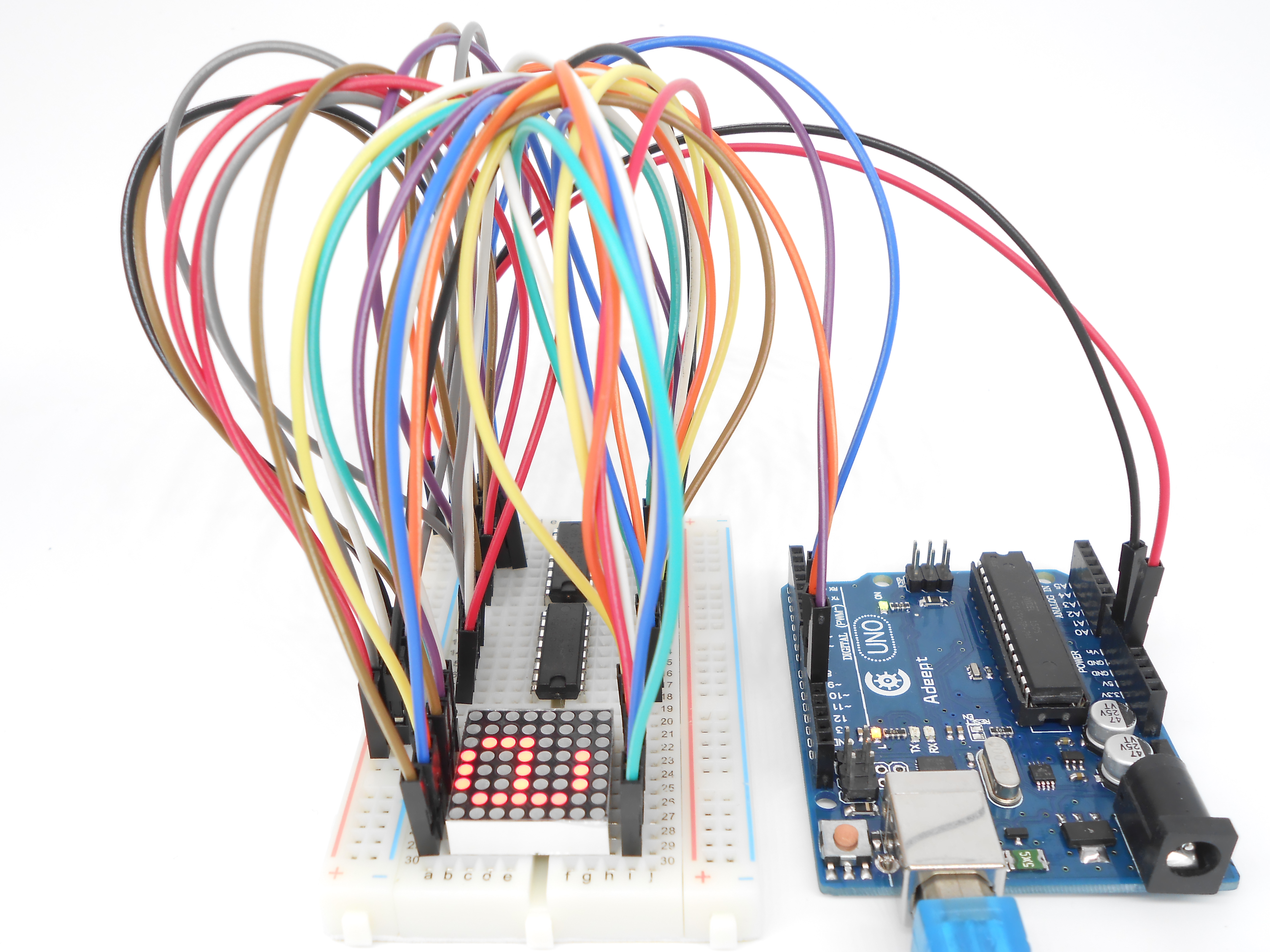
Step 1: Build the circuit (Make sure that the circuit connection is correct and then power, otherwise it may cause the chips to burn.)
Step 2: Program
/***********************************************************
File name: 25_ledMatrix.ino
Description: you can see a rolling “Adeept” should be displayed
             on the dot matrix display.
Website: www.adeept.com
E-mail: support@adeept.com
Author: Tom
Date: 2015/05/02
***********************************************************/

const int latchPin = 12; //Pin connected to ST_CP of 74HC595
const int clockPin = 8;//Pin connected to SH_CP of 74HC595
const int dataPin = 11; //Pin connected to DS of 74HC595
//Column scanning
int data[] = { 0x00,0x00,0x00,0x00,0x00,0x00,0x00,0x00,//Null
              0x00,0x3E,0x48,0x88,0x88,0x48,0x3E,0x00, //A
              0x00,0x00,0x0C,0x12,0x12,0xFE,0x00,0x00, //d
              0x00,0x00,0x7C,0x92,0x92,0x92,0x70,0x00, //e
              0x00,0x00,0x7C,0x92,0x92,0x92,0x70,0x00, //e
              0x00,0x00,0xFE,0x90,0x90,0x60,0x00,0x00, //p
              0x00,0x00,0x10,0x10,0x7E,0x12,0x10,0x00, //t
              0x00,0x00,0x00,0x00,0x00,0x00,0x00,0x00  //Null
              };

//Line scan
unsigned char  tab[]={0x7f,0xbf,0xdf,0xef,0xf7,0xfb,0xfd,0xfe};

void setup ()
{
  //set pins to output
  pinMode(latchPin,OUTPUT);//Set digital 12 port mode, the OUTPUT for the output
  pinMode(clockPin,OUTPUT);//Set digital 8 port mode, the OUTPUT for the output
  pinMode(dataPin,OUTPUT); //Set digital 11 port mode, the OUTPUT for the output
}

void loop()
{
    for(int n = 0; n < 56; n++) //Send column scanning cycle data
    {
        for(int t=0;t<100;t++)  //Control data scrolling speed
        {
            for(int num=n; num < 8+n; num++)//8 columns of data sent to a dot matrix
            {
                shiftOut(dataPin,clockPin,MSBFIRST,data[num]); //Send column data to a dot matrix
                shiftOut(dataPin,clockPin,MSBFIRST,tab[num-n]);//Send line data to a dot matrix
                //The rising edge of the data shift
                digitalWrite(latchPin,HIGH); //Output control latch HIGH
                digitalWrite(latchPin,LOW);  //Output control latch LOW
            }
        }
    }
}
Step 3: Compile the program and upload to Arduino UNO board
Now, you can see a rolling “Adeept” should be displayed on the dot-matrix display.
Summary
In this experiment, we have not only learned how to operate a dot-matrix display to display numbers and letters, but also learned the basic usage of 74HC595, then you can try operating the dot-matrix display to show other images.